|
©Copyright
1997-2010
Johnson
Kinetics, Inc.
All
Rights Reserved
Pages
best printed
in
Landscape


|
|
VibroTactile Stimulation
VibroTactile Stimulation allows a person to feel
a very wide range of sensations through pressure receptors in their skin
and body. JKI has developed its VTS product capability to producing
the many effects possible for a variety of applications. VTS drivers
are capable of driving several different types of VibroTactor elements
including Off-Center Motors, Buzzers, Coil-Based VibroTactile Elements,
and RamTactor Elements.
| This page features VibroTactile
Stimulation (VTS) hardware and details specifications and options of JKI's
family of custom built devices.
JKI Introduces the TacWave
Line of Tactile Stimulator Drivers. TacWave includes both Vibro and Electro
Tactile Systems. |
| If you would like General Information on Tactile
Stimulation (Both ETS & VTS), please visit our Tactile Section. |
 |
|
TacWave
VTS Drivers:
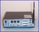
| A medium output configurations are
shown to the right. Model 301A has 4-12 outputs in 4 groups
of quick-connected cables. Several different Arrays can be connected
at the same time provided their drive specifications are similar.
Inputs for manual control, dual kill switches, internal/external grounds,
operating mode inputs, and standard LED status indicators are standard.
RF telemetry control is optional. |
<
vts.12.gif > |
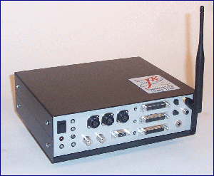
| A high output configuration is shown
to the right. Model 312C has 96 total outputs; 36 channels
in three groups of quick-connect and 60 channels in three sets of DIN cables
( built specifically for high count vests or chairs ). Inputs for
manual control, dual kill switches, internal/external grounds, dual operating
mode inputs, self testing of status of cable indicators, and standard LED
status indicators are standard. RF telemetry control is optional. |
 |
TacWave VTS Driver Special Features:
-
Manual, PC, Automated, Closed-Loop Control Options
-
Units use a dedicated pulse train / waveform generator
and can synthesize any pattern through on-board or controlled means
-
Wide channel count ( minimum of 4 Ch ) in custom
applications
All TacWave VTS Drivers Include:
| Fast Connect Connectors per Power
Range |
Grouped I/O Connectors |
| (2) Triple-Acting Kill Switches |
Operating Mode Select |
| External Power Supply |
High Impedance Communication |
| Isolation Buffered Outputs |
16 Embedded Patterns |
| Heat Dissipation Measures |
Use and Care Manual |
| Front Panel Operation / Status
LEDs |
TSComm Protocol Description |
| Desktop / Rack Mount Enclosure |
Dedicated Waveform Generation |
VTS Driver Options Include:
| Mapped Input Sensor Processors |
Additional Embedded Patterns |
| Multi-Port I/O Connectors |
Cascaded Operation |
| RF Telemetry / Control |
Multi-Driver Synchronization |
| Reduced Function Controllers |
Presentation / Carry Case |
VTS Driver Enclosure Specifications:
| Number of Output Channels |
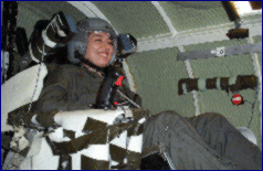
Test Subject Responding to VTS |
| Power Output Per Tactor |
| Any Other Outputs (relays, open
drain, timing, etc. ) |
| Typical Array Outputs ( 4, 8, 12,
2x12, 48, etc. ) |
| Alternative Inputs ( Sensors, Control,
Digital, Serial, etc. ) |
| Size / Weight Requirements ( if
any ) |
| Enclosure Type (Miniature, Metal,
Plastic, Rack Mount etc.) |
| Typical Method Control ( PC, MCC,
Handheld, Panel, etc.) |
| Any other Special Features ( High
'G', Waterproof, etc. ) |
VTS Elements and Arrays:
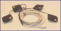 VTS
Vibration Elements and subsequent arrays are built to order and include
a variety of features for many applications. Three primary VibroTactor
Elements are typically used. The off-center motor based elements,
coil-based VibroTactors, and JKI's own long shaft based RamTactors each
have different performance specifications, physical dimensions, maximum
stimulation levels, power loading, and tactile effects. VTS
Vibration Elements and subsequent arrays are built to order and include
a variety of features for many applications. Three primary VibroTactor
Elements are typically used. The off-center motor based elements,
coil-based VibroTactors, and JKI's own long shaft based RamTactors each
have different performance specifications, physical dimensions, maximum
stimulation levels, power loading, and tactile effects.
Off-Center Motors.
Off-Set Motor Based Vibration Elements.
These elements are fairly common due to advantages of lower cost, predictable
repines and easy driving stages. Often referred to as 'Buzzer' units,
Off-Set Motor based elements have only one dimension of output, increasing
the voltage increases the tuns of the weight and the frequency and amplitude
of the vibration. The response time is poor |
Vibrotactors.
These standard VTS elements are coil based with
an in-line magnet. Due to the fact that you are driving these directly,
you have separate control of timing, response, amplitude, frequency,
and pulse train. Each pulse is felt separately, allowing great resolution
of sensation. These elements are capable of putting out a great deal
of heat but are very robust. |
RamTactors.
These long shaft variations on JKI's Vibrotactor
elements are impact based, not vibration based. A magnetic core is accelerated
towards the tactile end and energy propagated through whatever material
there is to the user. A great advantage of RamTactors are the ability
to be mounted in seats or similar structures where depth and heat generation
is not an issue and you may need to get a sensation through thick layers
of clothing or in frequency banks different that the ambient. This
is especially important in heavy vibration environments. The maximum
frequency is decreased in this mode, but still present in vibration mode. |
VTS arrays require a bit more support than our
ETS units. Weight, heat are issues to be addressed in each application.
Choose from these configurations or specify your own according to your
prospective mapping / applications including vests, forearm, soles, neck,
finger, and others.
Support Accessories:
 There
are several accessories for VTS systems including various types of kill
switches, stimulation pattern simulators, power mapped outputs, low frequency
music synchronizers, and others. There
are several accessories for VTS systems including various types of kill
switches, stimulation pattern simulators, power mapped outputs, low frequency
music synchronizers, and others.
VTS Array / Tactor Specifications:
| Size and Range for Flexible Garment
Based Arrays |
| Verify the Total Channel Number |
| Connectors (with respect to your
Driver I/O) |
| Power Level |
| ( Impact Level ) |
| Temperature Tolerance - Threshold
/ Heat Dissipation Measures |
| Auto Detect of Heat Threshold |
| Cable Length / Strain Relief (if
needed) |
| Tactor Shape, Area, depth |
| Tactor Element Impact / Weight
(depth of penetration) |
TacWave Controllers:
All TacWave, ETS, VTS, and LSAC systems can be
controlled through the TSComm protocol. This protocol is built into
our line of Manual Control Consoles (MCCs), Hand Controllers (HCs), and
can be generated by a computer's serial or USB port.
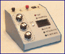
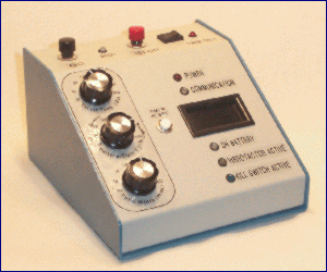
| This Manual Control Console
( MCC ) unit was designed for test and experimentation, as shown to the
right. It features isolated TSComm Syntax communications with a TacWave
VTS Driver, multiple LED displaces and indicators, separate adjustment
for three primary settings. The desktop unit also included a built
in timer to control timed responses to experimental input. Kill Switch
input from the wearer triggered time-out alarms and was a way to get hard
time data from experiments. |
 |
MCC Special Features:
-
Timed self monitoring of the VTS driver to insure
communications
-
Auto shutdown based on critical settings, responses,
or kill switch activation
-
Buffering for PC Control/Response and Instrumentation
Lines
-
Adaptable settings control for embedded pattern
-
Configuration control for various / multiple Tactor
Arrays / Fixed Mount Inputs
//
|
|


